|
Pin Shapes
ABox2 uses several different shapes to connect objects together.
The table below shows them all.
| Inputs |
Analog |
 |
 |
Edge
Detecting
(Triggers) |
pos |
 |
| neg |
 |
| any |
 |
Logic
Level
(Gates) |
pos |
 |
| neg |
 |
| Outputs |
Analog |
 |
 |
| Logic |
bipolar |
 |
| digital |
 |
|
Input pins receive data from other objects.
You can make only one connection to an input pin.
The letter on the pin will tell you what it's for.
Hover the pin and look at the status bar for more details.
Analog inputs are always triangles.
The object will look at the exact value of the signal and decide what to do.
Edge Detecting inputs (also called triggers) are always circles.
These inputs do not see the actual signal value.
Instead they look at when the signal crosses zero and cause the object to do something.
There are three flavors of trigger inputs: positive to negative, negative to positive, and both.
Logic Inputs (also called gates) are always diamonds.
Like the edge detecting inputs, logic inputs do not respond to the actual value of the signal.
Instead they look at whether the signal is negative or positive and enable the object to do something.
There are two flavors of gates, positive and negative.
Outputs send data to other objects.
You can connect any number of inputs to an output.
Analog outputs have a letter or an = symbol, but never a shape.
These pins may output any value but are designed to emit values between +1 and -1.
Logic outputs can only output three values, -1, 0, and +1.
There are two flavors of logic outputs, bipolar emits only +1 and -1, digital emits only 0 and -1.
|
|
Making Connections
Connecting objects together is simple.
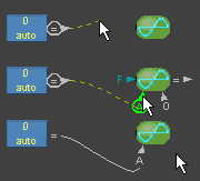
Left click on the pin you want to connect.
Move the mouse to the pin you want to connect to.
Let up on the mouse.
ABox2 will show you if it's OK to connect by turning the pins green.
If you're not supposed to connect, the pins will turn red and the status bar will tell you why.
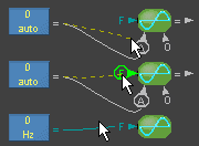
You can connect many input pins to one output pin.
Click first on the unconnected input, drag it over to the output, release the mouse.
|

|
|
Moving Connections
If you want to move a connection to someplace else, do the same thing.
Left click on the connected pin.
Move the mouse to where you want to reconnect to.
Let up on the mouse.
You can move most connections, but not all.
The status bar will tell you why.
|

|
|
Unconnecting
There are two ways to unconnect pins.
Hover the pin, and press Delete.
Right click on the pin to summon the Connection Panel, then choose Unconnect.
|
Mouse Action
ABox2 assumes that:
If you left click on an unconnected pin, you want to connect it.
If you left click on a connected pin, you want to move the connection somewhere else.
|
|
The Connection Panel
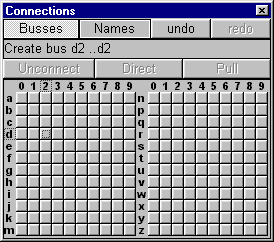
Use this panel to attach to busses, set names for busses, unconnect pins and convert connections to busses.
Busses are used to reduce circuit clutter caused by connecting lines.
The panel has two modes, Busses and Names.
Summon the connection panel by right clicking on a pin.
In bus mode you may create, transfer, rename, re-assign, or unconnect depending of the pin you clicked to summon the panel.
|

|
|
Bus Names
In large a circuit with many different busses,
it can be difficult to remember what a particular bus was for.
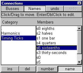
To help with this, ABox2 lets you assign names to busses.
The names will appear on the status bar when the bus is hovered.
Bus names have two parts: A category, and a member name.
The category is not required, but is useful for busses with a similar signal type.
Click and drag to move members to different categories.
Use the Tab key to switch between panes.
Use the arrow keys to end editing a name.
|

|
|
Bus Navigation
These keys let you follow the connections of a bus.
Home, go to the first connection.
Page Up, go to the previous connection.
Page Down, go to the next connection.
Use Undo to get back to where you started.
|
Moving Pins
As a final touch to your circuit, you can arrange pins by moving them around their objects.
Right click and drag the desired pin.
The pin will try to point at the mouse.
|